
A Technicians Guide to Pickup Color Codes: 4 conductor edition
I'm a big fan of 4-conductor pickup wires. They offer unparalleled ease of installation and the flexibility to customize wiring configurations, making them indispensable when pairing pickups from different manufacturers. My main frustration, however, is the lack of a standardized color code. Manufacturers are free to use any color scheme they choose, and some even vary it by model or year, which is incredibly annoying.
We will start with the easy bit as I can guess that 99% of you just want to know what your brands color is!

Are you new to wiring and just curious about pickup wires? Click this link
What happens when you don't know the color code?
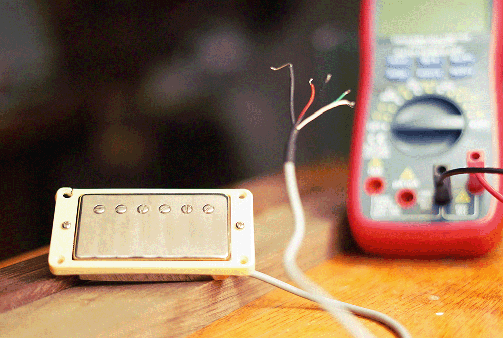
Imagine you've acquired a humbucker set from a defunct boutique builder or a generic set with no instructions. How do you decipher its color code? We'll explore this common real-world scenario, armed with only a multimeter.
 Step 1: Find the individual Coils.
Using the multimeter figure out what colors go with what coil. In this example.
- Red and Black makes one coil (3.86K)
- White and green make the other coil (3.89K)
Step 2: Figure out the Phase:
For proper pickup function, both coils must be a certain phase. To test this, connect a multimeter to a single coil. Place a metal object, such as a screwdriver, flat against the pole pieces and observe the multimeter for a jump (up or down). This also helps identify the slug and screw coils.
We began with the green and white wires. Touching the pole pieces confirmed this was the screw coil. With the green wire connected to the multimeter's positive terminal and the white wire to ground, the coil's reading momentarily increased before returning to normal. Repeat this test multiple times to ensure a consistent jump.
Now, regarding the Slug coil: When the Black wire is connected to the Positive terminal and the Red wire to the Ground, the Slug coil's output decreased. This indicates that the coil is out of phase with the other coil. Therefore, when creating a series link, we need to reverse the color coding so that Red becomes our "Positive" and Black becomes our "Negative."
It's important to clarify, before everyone's favorite awkward “well actually” guy angerly chimes in, that these "positive" and "negative" labels are for mental reference only. Pickups function as AC transformers, meaning they do not have a fixed positive and negative polarity.
So to put it in a readable format.
- Screw Coil + = Green
- Screw Coil - = White
- Slug Coil + = Red
- Slug Coil - = Black
To operate the humbucker, connect the two “negative” wires to create a series link. This allows you to select which coil functions as the first and last in the signal path. For instance, if green is designated as hot and red as ground, doing a phase test shows the multimeter reading increasing. Ensure the same color coding is applied to the other pickup to maintain phase consistency.

Example of messing up the phase.
If your pickup sounds thin and weak after installation, it's likely due to incorrect phase wiring. To correct this, reverse the labelled positive (+) and negative (–) connections on one of the coils. For example, on the Slug coil, if you previously wired Red as + and Black as –, swap them so Black is + and Red is –. Then, re-test it.
Readable Format
- Hot = Green
- Series Link = White and Red Soldered together
- Ground = Black

I am installing this unknown pickup with another brand.
As previously stated, there is no standardized color code or, more importantly in this context, a standardized magnet direction. It's possible to have two pickups with the same color code but reversed magnet directions. In such cases, we must determine the individual humbucker phase, just as we did for individual coils. For example, if the Neck humbucker shows an upward phase when touched and the Bridge pickup shows a downward phase, we simply need to reverse the positive and negative wires of one of the pickups. So, for the Bridge pickup, where green was previously positive and red was negative, we would now wire red as hot and green as ground.
Here's the readable format.
Neck pickup (Brand A)
-
Green is +
-
White/black is our Series link.
-
Red is -
Bridge pickup (Brand B)
-
Red is +
-
White/black is our Series link.
-
Green is -
But wait, what about the Bare wire?
No matter what, the bare wire is always going to be grounded.
Read more
Knobs the Silent killers of Potentiometers
I know what you are thinking. This is clickbait. But its not. At this time we have sold tens of thousands of kits that we worked really hard to make audibly perfect. But, we started noticing a patt...
Read more
Our new redesigned Jimmy Page Kit
The Jimmy Page circuit can be a game changer for people, especially when you are just starting out discovering wiring. For me it was. This is the circuit that got me addicted to learning wiring bac...
Read more
Leave a comment
This site is protected by hCaptcha and the hCaptcha Privacy Policy and Terms of Service apply.